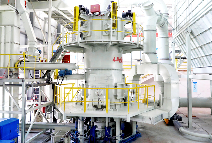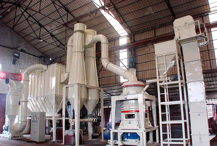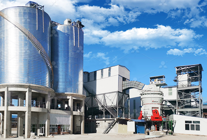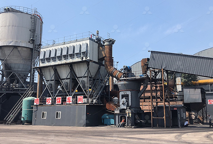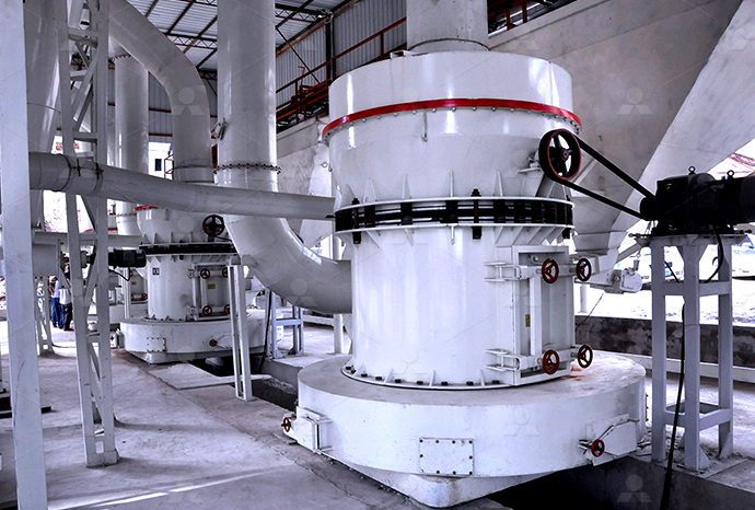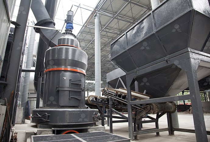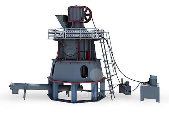
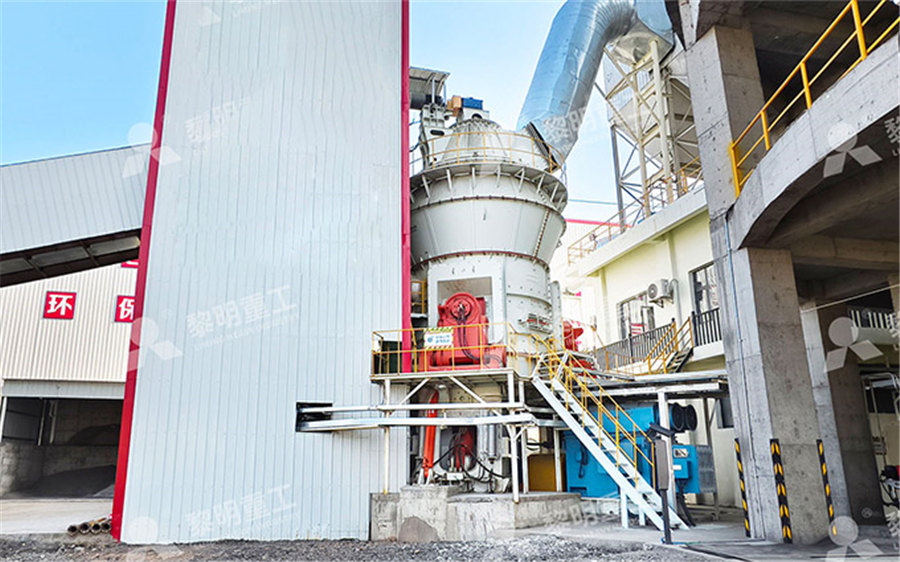
Pulverized coal processing technology diagram
Schematic diagram of coal pulverizer model: (a ResearchGate
this section, an overview of the typical design of a vertical roller coal pulverizer is analysed and discussed A schematic diagram of the used coal pulverizer is shown in Fig 1Process flow diagram for a pulverized coal power plant retrofitted with MEA absorption technProcess flow diagram for a pulverized coal power plant retrofitteEl actual despliegue de las energías renovables a nivel mundial, caracterizado por un sostenido incremento de la capacidad instalada de generación con fuentes eólicas y solares, configura Advanced Pulverized Coal process flow diagramIn this paper, modern and reliable process modeling techniques, ie, multiple linear regression (MLR), artificial neural networ schematic process flow of the pulverized coal powerThe schematic process flow of pulverized coal power plant
.jpg)
Pulverised Coal an overview ScienceDirect Topics
Steps in the process are (1) mining of the coal from nearsurface or deep mines, (2) transporting crushed coal several centimeters in size to the power station, (3) pulverizing the coal to a Pulverized coal combustion (PCC) is the most widely used technology for coal power generation In this process, coal is milled, pulverized, and injected in the boiler with air to allow Pulverised Coal Combustion an overview ScienceDirect TopicsA diagram of the CWM manufacturing process is shown in Figure 1 and can be handled as an easytotreat liquid Conventional coal slurry, without additives could be piped but, due to an 4C2 Coal Water Mixture Production Technology (CWM)static performance of pulverizers, which play a very important role in fuel burning process as pulverized fuel size dominates burnout behaviour, has been improved This paper gives an Advanced Development of Pulverized Coal Firing Technologies
Advances in pulverised fuel technology: understanding coal
2023年1月1日 This chapter discusses research that has contributed to improved understanding of pulverized fuel (PF) technology The processes studied are the grinding of PF in power 2021年2月12日 A coal burner is composed of a pulverized coal machine, combustion machines like a combustion chamber and air supply system, and a control system The coal is pulverized and mixed with air before being ignited Pulverized coalburner PPT SlideShareProcess flow diagram for a pulverized coal power plant retrofitted with MEA absorption technology for CO2 capture Adapted from Ciferno (2007) Note: the new equipment isProcess flow diagram for a pulverized coal power plant 2022年12月1日 By using this coprocessing technology, the feed ratio of crude oil and coal can be 1:1, the coal conversion rate can be over 99%, the light oil (oil and aromatics) yield was over 70%, and the end Investigation of the coprocessing technology of
Study of reaction and flow characteristics in multinozzle pulverized
CIESC Journal ›› 2023, Vol 74 ›› Issue (8): 32663278 DOI: 1011949/04381157 • Fluid dynamics and transport phenomena • Previous Articles Next Articles Study of reaction and flow characteristics in multinozzle pulverized coal gasifier with coprocessing of wastewaterDownload scientific diagram Simplified process flow diagram of tangentially fired pulverizedcoal boiler from publication: Prediction of NOx Emission from Coal Fired Power Plant Based on Real Simplified process flow diagram of tangentially fired According to the principle of influence on pulverized coal, this technology is based on a different For each of these sections, a mass flow and heat balance is calculated according to the diagram shown in Fig 5 Download: Download high Cocombustion of coal processing waste, oil refining waste and municipal solid waste Novel technology of electric combustion of pulverized coal and The use of oxycoal enables around 20% increase in coal injection and help reduce coke quantities accordingly (Worrell et al, 2010) With 170 200 kg/tHM pulverized coal injection, coke consumptions as low as 286 320 kg/tHM has been achieved in modern blast furnacesPulverized Coal Injection Industrial Efficiency Technology
The schematic process flow of pulverized coal power plant
Download scientific diagram The schematic process flow of pulverized coal power plant from publication: Optimization of a 660 MW e Supercritical Power Plant PerformanceA Case of Industry 40 footprint and costs of the coalbased integrated gasification combined cycle (IGCC) technology relative to the conventional pulverized coal (PC) technologies The technology options evaluated are restricted to those that are projected by the authors to be commercially applied by 2010 The IGCC plant configurations include coal slurrybasedEnvironmental Footprints and Costs of CoalBased Integrated 2020年7月1日 The schematic diagram of pulverized coal preheating equipment is shown in Fig 1 [30] In this paper, utilizing both digital imaging technology and image processing technology, the combustion condition of the preheated pulverized coal in the raceway is detectedMeasurement study of preheated pulverized coal injection on combustion Download scientific diagram Heat Balance Diagram of a typical Super Critical Pulverized Coal Power Plant with an efficiency of 368% (values taken from DOE/NETL, 2010) from publication: Water Heat Balance Diagram of a typical Super Critical Pulverized Coal
.jpg)
Three combustion stages of pulverized coal jet
Download scientific diagram Three combustion stages of pulverized coal jet from publication: Computer image processing and neural network technology for boiler thermal energy diagnosis The 2024年10月1日 Pyrolysis and gasification were common methods for the multistage utilization of pulverized coal, generating two high application products of tar and syngas [2, 3], which were the raw materials of chemical productionThe coalbased polygeneration technology coupling with pyrolysis or gasification aimed to realize the multistage utilization of coal resources and An experimental investigation on gasificationpyrolysis coupling coal particles and the mill chassis to the outlet temperature » » » ¼ º « « « ¬ ª ( ) ( ) ( ) ( ) ( ) 1 ( ) 10 11 C Tw L Et C w t T C w t T t C w t T T t dt d c out out m c v c a air air air in m w c a out U T U T (9) = Mass of unpulverised coal on the table (kg) = Mass of pulverized coal on the table (kg) = Mass of pulverized coal Modeling and Control of Coal MillDownload scientific diagram Schematic diagram of the pulverized coal combustion furnace from publication: Research on the slagging characteristics of blended coals in a pilotscale furnace Schematic diagram of the pulverized coal combustion furnace
.jpg)
Schematic diagram of coal power plant operation
Download scientific diagram Schematic diagram of coal power plant operation from publication: Optimization of a 660 MWe Supercritical Power Plant PerformanceA Case of Industry 40 in the Data 2020年3月25日 Various types of coal are available such as lignite, subbituminous coal, bituminous coal, and anthracite The gasification process involves two distinct stages: coal devolatilization followed by char gasification, which is specific to the conditions of the reactionCoal Gasification Handbook of Gasification Technology2021年2月12日 The coal pulverizer will crush the coal into pulverized coal Water is heated, turns into steam, and spins a steam turbine, which drives an electrical generator In the coal burner, the pulverized coal mixes with air (Highspeed airflow is generated by the draft fan on the coal burner), and is ignited by the oilburning igniterPulverized coalburner PPT SlideShareFuel preparation for a pc boiler occurs in a mill, where coal is typically reduced to 70% through a 200mesh (74μm) screen Figure 2 shows a particlesize distribution from a bowlmill grinder typically used in power plants A typical utility specification for particle size distribution of the coal is that 70% of the mass should pass through a 200mesh screen, which is equivalent to 70% Pulverized Coal Boiler an overview ScienceDirect Topics
.jpg)
Fundamental Reaction Characteristics of Pulverized Coal at J
pulverized coal injection and the combustion efficiency in the tuyere Ariyama et al6) studied movement of pulverized coal particles, based on the direct observation Shen et al7) tried to improve pulverized coal combustibility by addition of KMnO 4 as a catalyst Jamaluddin et al8) and Tsuge et al9) tried to develop a mathematical model 2021年11月2日 In the pulverized coal injection (PCI) process of a blast furnace (BF), intensifying the combustion of pulverized coal in the raceway and tuyere is the key to increasing the injection ratio 3,4 In addition to widely used technologies that cooperate with PCI, such as oxygen enrichment and high temperature of hot blast air, 5,6 the catalytic combustion technology for Combustion Characteristics of Coal for Pulverized Coal Injection 2023年1月13日 The paper provides an outlook on future directions of research and the possible applications for pulverized coalfired boilers One potential direction for future research is to focus on the ways (PDF) Pulverized CoalFired Boilers: Future Directions of Scientific Coal pulverization and mixing with water/additives by a pulverizer Clean Coal Technologies in Japan 70 4C2 Coal Water Mixture Production Technology (CWM) Technology overview 1 Coal slurry overview ˜ The fact that coal is a solid causes some challenges; it requires more complex handling than a fluid does, environmental4C2 Coal Water Mixture Production Technology (CWM)

Fundamental Reaction Characteristics of Pulverized Coal at J
pulverized coal injection and the combustion efficiency in the tuyere Ariyama et al6) studied movement of pulverized coal particles, based on the direct observation Shen et al7) tried to improve pulverized coal combustibility by addition of KMnO 4 as a catalyst Jamaluddin et al8) and Tsuge et al9) tried to develop a mathematical model Download scientific diagram Six phase model interactionsPCI: Pulverized coalPCH: Pulverized charcoalsolid line indicates full interactions and dotted line for mass and heat exchange only Six phase model interactionsPCI: Pulverized coal Download scientific diagram 3 Schematic diagram of an ideal coalfired thermal power plant Adapted from https:// waterusgsgov/edu/ from publication: Polycyclic Aromatic Hydrocarbons (PAHs 3 Schematic diagram of an ideal coalfired thermal powerDownload scientific diagram EPA downfired pulverized coal combustor from publication: Comparison of Particle Size Distributions and Elemental Partitioning from the Combustion of Pulverized EPA downfired pulverized coal combustor Download Scientific Diagram
.jpg)
Combustion visualization analysis of alternative fuels in the
2024年9月15日 Pulverized coal injection technology uses up to 250 kg per ton of hot metal and is currently optimized to the range of 150–180 kg per ton of hot metal, similar VanKrevelen diagram of the samples which emits light with a higher intensity than that of the cloud Image data processing was performed to analyze combustion 2021年7月1日 The paper presents options for almost wastefree technologies for joint and separate processing of pulverized metallurgical and coal waste based on a jetemulsion melting gasifier with obtainment Mathematical models based analysis of the efficiency of joint A new coal combustion technology for a largescale power plant is required to be applicable to various kinds of coal An oxygenblown pulverized coal combustion experiment was investigated with a Schematic diagram of the pulverized coal burnerPulverised coal power plants account for about 97% of the world's coalfired capacity The conventional types of this technology have an efficiency of around 35% For a higher efficiency of the technology supercritical and ultrasupercritical coalfired technologies have been developed These technologies can combust pulverised coal and produce steam at higher temperatures Pulverised Coal Combustion with higher efficiency Climate Technology
Development of Woody Biomass High Ratio CoFiring Technology
Development of Woody Biomass High Ratio CoFiring Technology for Pulverized Coal Boiler Plants TAMURA Masato General Manager, Combustion Engineering Department Figure 2 is a schematic diagram of the smallscale combustion test facility The vertical cylindrical furnace has a maximum heat capacity of 12 MW, an inner diameter of 1 2022年12月1日 By using this coprocessing technology, the feed ratio of crude oil and coal can be 1:1, the coal conversion rate can be over 99%, the light oil (oil and aromatics) yield was over 70%, and the end Investigation of the coprocessing technology of CIESC Journal ›› 2023, Vol 74 ›› Issue (8): 32663278 DOI: 1011949/04381157 • Fluid dynamics and transport phenomena • Previous Articles Next Articles Study of reaction and flow characteristics in multinozzle pulverized coal gasifier with coprocessing of wastewaterStudy of reaction and flow characteristics in multinozzle pulverized Download scientific diagram Simplified process flow diagram of tangentially fired pulverizedcoal boiler from publication: Prediction of NOx Emission from Coal Fired Power Plant Based on Real Simplified process flow diagram of tangentially fired
.jpg)
Novel technology of electric combustion of pulverized coal and
According to the principle of influence on pulverized coal, this technology is based on a different For each of these sections, a mass flow and heat balance is calculated according to the diagram shown in Fig 5 Download: Download high Cocombustion of coal processing waste, oil refining waste and municipal solid waste The use of oxycoal enables around 20% increase in coal injection and help reduce coke quantities accordingly (Worrell et al, 2010) With 170 200 kg/tHM pulverized coal injection, coke consumptions as low as 286 320 kg/tHM has been achieved in modern blast furnacesPulverized Coal Injection Industrial Efficiency TechnologyDownload scientific diagram The schematic process flow of pulverized coal power plant from publication: Optimization of a 660 MW e Supercritical Power Plant PerformanceA Case of Industry 40 The schematic process flow of pulverized coal power plantfootprint and costs of the coalbased integrated gasification combined cycle (IGCC) technology relative to the conventional pulverized coal (PC) technologies The technology options evaluated are restricted to those that are projected by the authors to be commercially applied by 2010 The IGCC plant configurations include coal slurrybasedEnvironmental Footprints and Costs of CoalBased Integrated
.jpg)
Measurement study of preheated pulverized coal injection on combustion
2020年7月1日 The schematic diagram of pulverized coal preheating equipment is shown in Fig 1 [30] In this paper, utilizing both digital imaging technology and image processing technology, the combustion condition of the preheated pulverized coal in the raceway is detectedDownload scientific diagram Heat Balance Diagram of a typical Super Critical Pulverized Coal Power Plant with an efficiency of 368% (values taken from DOE/NETL, 2010) from publication: Water Heat Balance Diagram of a typical Super Critical Pulverized Coal Download scientific diagram Three combustion stages of pulverized coal jet from publication: Computer image processing and neural network technology for boiler thermal energy diagnosis The Three combustion stages of pulverized coal jet


